
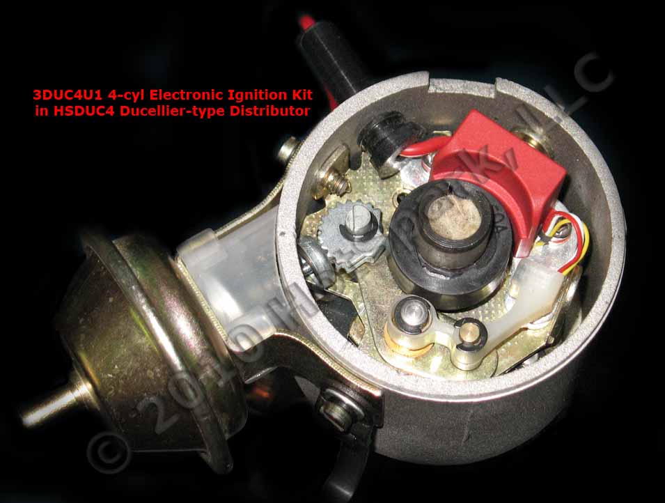
Installing the 3DUC4U1
Electronic Ignition Conversion Kit
in Ducellier 4-Cylinder Distributors
Installing the 3DUC4U1
Electronic Ignition Conversion Kit in 4-Cylinder Ducellier Distributors
(12-volt, negative ground only):
1. Remove points, condenser and condenser wire from the vehicle.
2. Attach the red lead of a voltmeter to the coil's positive ( + or 15)
terminal. Attach the voltmeter's black lead to engine ground. With the ignition
switch on, engine not running, measure the voltage at the coil's positive ( + or
15) terminal. The reading should be somewhere around +11 to +13 volts. If
voltage is too low or there’s no reading, the battery’s terminals or ground
connection may be corroded and need cleaning. Some vehicles have a resistor wire
running from the ignition switch to the coil’s + terminal. If this resistor wire
drops the voltage below 9 volts or so, you may need to run a non-resistor wire
from the ignition switch to the coil’s + terminal or run a +12V wire directly
from the ignition switch to the red Hot-Spark ignition wire. Make sure that the
ignition switch terminal to which you connect this wire has power only when the
ignition switch is in the ON position.
Coil: 4-cylinder ignition kits must be used with a coil that has 3.0 Ohms or
more primary resistance.
Test Maximum Charging System Voltage: If
the charging system voltage, measured at the coil’s positive terminal, is more
than 13.9 volts at any RPM level, the voltage regulator likely needs replacing.
Too much voltage can destroy the ignition module and other electronic
components. A maximum charging system voltage of 13.7 volts or so is plenty. A
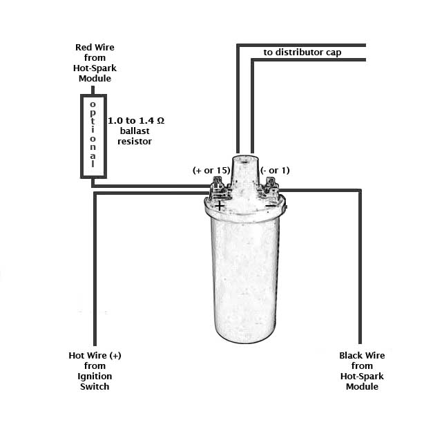
quick fix is to wire a 1.4
Ohm external ballast resistor between the coil's + terminal and the
HotSpark ignition's red wire. Adding the ballast resistor is cheap insurance
against voltage surges, etc.
To get the ignition running initially, only these wires should be attached to
the coil's + and - terminals:
A. +12 volts from the ignition switch to the coil's + terminal
B. Red Hot-Spark wire to the coil's + terminal
C. Black Hot-Spark wire to the coil's - terminal. DO NOT connect any +12-volt wire to the coil's - terminal. Connect only the
black Hot-Spark ignition wire to the coil's -
terminal. Do not connect the coil's - terminal
to ground.
D. The automatic choke and fuel shut-off valve may also need to be attached to
the coil's + terminal.
E. Generally, only the black Hot-Spark wire is attached to the coil's -
terminal. If a tachometer wire is usually attached to the coil's - terminal,
don't attach it until the timing has been set and engine is running properly. No
other wires should be connected to the coil's + and - terminals at this time.
F. Static timing, using an ordinary
12-volt test lamp, will not work. Attach a
stroboscopic timing light to the spark plug wire of cylinder number 1. With
engine rotated to TDC (0 degrees) on the firing stroke of Cylinder number 1,
ignition switch ON, turn the distributor until the timing light flashes. You may
need to turn the distributor left or right, a little at a time, until the engine
will stay running, so that you can set the timing with the engine running, using
a stroboscopic timing light, according to factory specifications.
G. For testing purposes, no other wires should be attached to the coil
terminals, except for the center high-tension lead to the distributor cap.
Timing the 3DUC4U1 Ignition Kit:
Ignition Timing: The old method of setting the timing statically, using a simple 12-volt test lamp, doesn't work with electronic ignition, as it did with points. Use a stroboscopic timing light. Timing should be set initially at about 30° BTDC at about 3,000+ RPM. The distributor shaft rotates clockwise. The ignition timing should be checked with the engine running, using a stroboscopic timing light, ensuring optimum engine performance and economy. Paint a small line of white paint on both the reference pointer and the appropriate mark on the timing scale to make them more easily seen. With the engine running at the specified speed, the appropriate timing mark should be in line with the reference pointer. Rotate the distributor body counter-clockwise to advance the timing, or clockwise to retard it.
This ignition kit requires a 12-volt, negative ground electrical system.
Coil Required: Do not use a low-resistance coil that does not have the minimum primary resistance required by the ignition module, as stated in the instructions (minimum 3.0 ohms for 4- and 6-cyl or 1.5 ohms for 8-cyl, assuming a 12-Volt electrical system). The coil resistance regulates the current in the ignition module/coil circuit. Too little coil primary resistance resistance results in too much amperage going to the ignition module, which can overheat the electronics. The failure may not happen immediately, but the excess heat will shorten the life of the ignition module electronics. How long the electronics will last depends on how much heat is generated. It could be a matter of a couple of hours to a few hundred hours, depending on temperature.
To measure coil primary resistance: Label and remove all wires to coil (
+ or - ). Using a common digital multimeter in the 200 Ω mode, cross the red and
black leads of the Ohmmeter. Allow 10 seconds or more for the reading to settle
and write down the reading. Still in the 200 Ohm mode, measure between coil’s +
and - terminals. Allow a few seconds for the reading to settle, until it
stabilizes. Subtract the previous reading, taken with the leads crossed, to
compensate for Ohmmeter’s inherent resistance. Do not use a low-resistance coil,
such as the MSD or Accel coil; they don’t have enough primary resistance for
this application. For best performance, the coil should also have 7,000 Ohms or
more secondary resistance (measured from coil’s + or – terminal to center high
tension terminal, in the 20K Ω mode of the Ohmmeter).
Ballast Resistor: If the coil's primary resistance is not quite enough or
is borderline, you can wire an external ceramic ballast resistor (with 1.0 to
1.4 Ohms resistance) between the coil's + terminal and the red HotSpark ignition
wire: www.Hot-Spark.com/1-HS17BR.htm . Adding the ballast resistor is cheap
insurance against voltage surges, etc.
Test the charging system's maximum voltage: Check the voltage reading at the coil's + terminal, engine running. If the voltage measures more than +13.9 volts, at any RPM level, you'll need to replace the voltage regulator, install a coil with 3 Ohms or more internal primary resistance and/or install a 1.4 Ohm external ballast resistor between the coil's + terminal and the HotSpark ignition's red wire.

© 2005-2025 Hot Spark®