
Installing the Hot-Spark Electronic Ignition Conversion Kit in Nippondenso Distributors
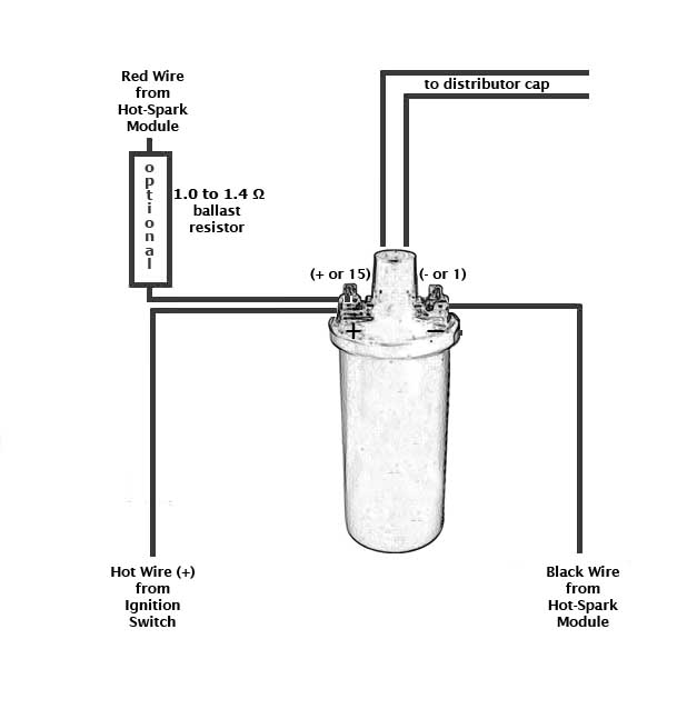
Warning: Reversing the red and black ignition wires will destroy the ignition module. The Hot-Spark module’s red wire connects to positive ( coil’s + terminal). The black wire connects to negative (coil’s - terminal). Remove the condenser and its wire from vehicle. Connect any other wires to the coil in their original positions. This module is designed for 12V negative ground applications only.
Test Maximum Charging System Voltage: If the charging system voltage, measured at the coil’s positive terminal, is more than 13.9 volts at any RPM level, the voltage regulator likely needs replacing. Too much voltage can destroy the ignition module and other electronic components. A maximum charging system voltage of 13.0 volts or so is plenty. A quick fix is to wire a 1.4 Ohm external ballast resistor between the coil's + terminal and the HotSpark ignition's red wire.
Make sure that the ignition wires have plenty of slack inside the distributor and are not rubbing on any moving parts. It’s best to use a small zip-tie, on the inside of the distributor, where the ignition wires exit, to keep the wires from being pulled into contact with moving parts. If you need to extend the length of the ignition wires, use 20-gauge (AWG) wire. Crimp tightly or solder all connections.
Remove points, condenser and condenser wire from distributor. Remove the condenser and its wire from the vehicle. Important: Clean the distributor’s breaker points plate thoroughly, so that the ignition module’s base plate makes good thermal contact with the distributor.
Coil Required: Do not use a low-resistance coil that does not have the minimum primary resistance required by the ignition module, as stated in the instructions (minimum 3 ohms for 4- and 6-cyl or 1.5 ohms for 8-cyl, assuming a 12-Volt electrical system). The coil resistance regulates the current in the ignition module/coil circuit. Too little coil primary resistance resistance results in too much amperage going to the ignition module, which can overheat the electronics. The failure may not happen immediately, but the excess heat will shorten the life of the ignition module electronics. How long the electronics will last depends on how much heat is generated. It could be a matter of a couple of hours to a few hundred hours, depending on temperature.
Ballast Resistor: If the coil's primary resistance is not quite enough or is borderline, you can wire an external ceramic ballast resistor (with 1.0 to 1.4 Ohms resistance) between the coil's + terminal and the red HotSpark ignition wire: www.Hot-Spark.com/1-HS14BR.htm
Check the voltage reading at the coil's + terminal, engine running. If the voltage measures more than +13.9 volts, at any RPM level, you'll need to replace the voltage regulator, install a coil with 3.0 Ohms or more internal primary resistance and/or install a 1.4 Ohm external ballast resistor between the ignition switch and the coil's + terminal. For best performance, the coil should also have a 7,000 Ohms or more secondary resistance (measured from coil’s + or – terminal to center high tension terminal, in the 20K Ω mode of the Ohmmeter).
Test Battery Voltage to Coil: With ignition switch ON, engine not running, check voltage at coil’s + terminal. The voltmeter should read somewhere around +11 to +13 volts. If voltage is too low or there’s no reading, the battery’s terminals or ground connection may be corroded and need cleaning or the battery may need charging. Some vehicles have a resistor wire running from the ignition switch to the coil’s + terminal. If this resistor wire drops the voltage below 9 volts or so, you may need to run a non-resistor wire from the ignition switch to the coil’s + terminal or run a +12V wire directly from the ignition switch to the red Hot-Spark ignition wire. Make sure that the ignition switch terminal to which you connect this wire has power only when the ignition switch is in the ON position.
Air Gap between Magnet Sleeve and Ignition Sensor: If you need to increase air gap slightly, hold ignition base plate away from distributor shaft while tightening set screw and/or loosen the two Allen head screws and retighten screws while lightly prying ignition module away from magnet sleeve. Do not over-torque these Allen screws. Black magnet sleeve should not rub against red ignition module, but exact gap is not critical. In rare instances, it may be necessary to gently pry red ignition module away from black magnet sleeve to keep them from rubbing together.
Ignition Timing: Set the ignition timing, with a stroboscopic light, to the distributor’s factory specification. The difference in distributor position with points vs. electronic ignition can be as much as 30 degrees or so clockwise or counterclockwise, so you’ll definitely have to reset the timing.
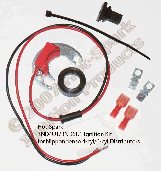
The 3ND4U1 and 3ND6U1 ignition kits are identical, except that the 3ND4U1 has a 4-cylinder magnet sleeve and the 3ND6U1 has a 6-cylinder magnet sleeve.
1. Turn off the ignition switch and/or remove the ground strap from the battery. Though not absolutely necessary, it is probably easiest overall to remove the distributor from the car before installing the Hot-Spark module. If the contacts in the inside of the distributor cap are worn or damaged, replace the distributor cap. Replace the rotor if it’s worn.
2. Remove distributor cap, leaving the plug wires in place, unless replacing the distributor cap as well.
3. Remove points, condenser and the condenser’s wire from the vehicle. Because the Hot-Spark kit does not modify the distributor, the points and condenser can be reinstalled at a later time.
4. Clean any grease or dirt thoroughly from the distributor’s points cam and the breaker points plate.
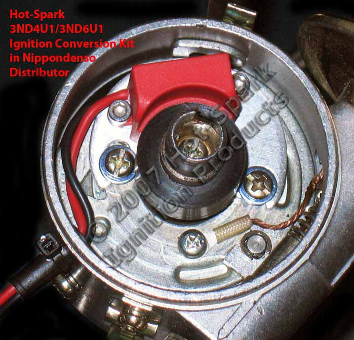
5. Clean the breaker plate thoroughly to provide a solid electrical ground and good thermal transfer. Apply a thin coat of the supplied thermal transfer paste to the bottom of the ignition base plate. Place the Hot-Spark module’s base plate onto the distributor’s breaker plate. The two screw holes should line up. The Hot-Spark module’s base plate should lie flat and snug on the distributor’s breaker plate. Insert the screws and tighten, while gently pressing the ignition module away from the distributor shaft.
The 3ND4U1 and 3ND6U1 ignition kits are identical, except that the 3ND4U1 has a 4-cylinder magnet sleeve and the 3ND6U1 has a 6-cylinder magnet sleeve. 3ND6U1: One of the screws and its washers attaching the 3ND6U1 ignition module to the distributor's breaker plate may be too tall to allow the magnet sleeve to seat fully without rubbing on the screw. You may need to replace this screw with another metric screw of the same size and thread pitch, but without washers or with only one thin washer.
6. If you need to increase the air gap slightly, hold ignition base plate away from distributor shaft while tightening set screw and/or loosen the two Allen head screws and retighten screws while lightly prying ignition module away from magnet sleeve. Do not over-torque these Allen screws.
7. Install magnet sleeve, with the larger opening down. Turn the magnet sleeve left and right, while pushing down firmly, until you can feel the distributor shaft cam lobes line up with the flat spots inside the magnet sleeve. Press down firmly until the magnet sleeve slides as far down as it will. Install the rotor on top of the magnet sleeve, making sure the rotor is aligned with the slot in the top of the distributor shaft. The rotor should slide all the way down and lock into place, so that it cannot turn independently of the distributor shaft. If you can still turn the rotor independently of the distributor shaft, the magnet sleeve and/or rotor is not seated all the way down.
8. Adjust the two Hot-Spark ignition wires so that they have plenty of slack inside the distributor and they’re not rubbing on any moving parts. See previous photo.
9. Reinstall the distributor.
10. Install the distributor cap.
11. The Hot-Spark module’s red wire connects to positive (coil’s + terminal). The black wire connects to negative (coil’s - terminal). DO NOT reverse the polarity of these wires or the ignition module will be destroyed.
12. Check all wire connections, including the two Hot-Spark wires and the spark plug and coil high-tension wires. If you need to extend the length of the wires, use 18- or 20-gauge wire. We recommend soldering all splices and connections, if you can, or crimp all connections tightly. Make doubly sure that all wires are connected to the proper terminals, etc. before reconnecting the battery or turning the ignition switch to the ON position. Make sure that all connectors are snug. Reconnect the battery and set the distributor timing statically.
13. You can set the timing statically to about 0° (TDC) at first, so that the engine will start. You may need to turn the distributor, a little at a time, right or left, to enable the engine to start and remain running. Time the engine with a stroboscopic light in the normal manner, to the factory timing specifications.
Setting Timing: This will probably be the last time you have to set the timing for a long time, so it’s worth it to spend the extra time and effort to set the timing absolutely spot-on accurately. An engine with its timing set to perfection will start with the slightest bump of the starter and purr like a kitten at idle – something to make you feel good every time you start the engine.
TDC = Top Dead Center, or 0° BTDC = Before Top Dead Center ATDC = After Top Dead Center
Timing the Nippondenso Distributor: Use a stroboscopic timing light and tach/dwell meter or tachometer. Static timing at around 0° (TDC) is suitable only for the initial adjustment, in order to get the engine running. To set the timing accurately, you must use a stroboscopic light connected to No. 1 cylinder’s spark plug wire, according to your engine’s tune-up specifications.
Distributor Cap and Rotor: Stock Nippondenso rotors and distributor caps work fine with the Hot-Spark module.
Spark Plug Gap: With the Hot-Spark ignition kit, the stock spark plug gap specification is fine. For racing purposes, you can increase the spark plug gap by about .005 inches, or .12 mm.
Using Hot-Spark Ignition with MSD Blaster: Refer to this diagram to use the Hot-Spark Ignition with the MSD (Multiple Spark Discharge) 6-Series Blaster:
https://www.Hot-Spark.com/Hot-Spark-MSD-6-Series.jpg
Wiring Installation Basics:
1. Remove points, condenser and condenser wire from the vehicle.
2. Attach the red lead of a voltmeter to the coil's positive ( + ) terminal. Attach the voltmeter's black lead to engine ground. With the ignition switch on, engine not running, measure the voltage at the coil's positive ( + ) terminal. The reading should be somewhere around +11 to +13 volts. If voltage is too low or there’s no reading, the battery’s terminals or ground connection may be corroded and need cleaning. Some vehicles have a resistor wire running from the ignition switch to the coil’s + terminal. If this resistor wire drops the voltage below 9 volts or so, you may need to run a non-resistor wire from the ignition switch to the coil’s + terminal or run a +12V wire directly from the ignition switch to the red Hot-Spark ignition wire. Make sure that the ignition switch terminal to which you connect this wire has power only when the ignition switch is in the ON position.
To get the ignition running initially, only these
wires should be attached to the coil's + and - terminals:
A. +12 volts from the ignition switch to the coil's + terminal
B. Red Hot-Spark wire to the coil's + terminal
C. Black Hot-Spark wire to the coil's - terminal. DO NOT connect any +12-volt wire to the coil's - terminal. Connect only the
black Hot-Spark ignition wire to the coil's -
terminal. Do not connect the coil's - terminal
to ground.
D. The automatic choke and fuel shut-off valve may also need to be attached to
the coil's + terminal.
E. Generally, only the black Hot-Spark wire is attached to the coil's -
terminal. If a tachometer wire is usually attached to the coil's - terminal,
don't attach it until the timing has been set and engine is running properly. No
other wires should be connected to the coil's + and - terminals at this time.
F. Static timing, using an ordinary 12-volt test lamp, will not work. Attach a stroboscopic timing light to the spark plug wire of Cylinder number 1. With engine rotated to TDC (0 degrees) on the firing stroke of Cylinder number 1, ignition switch ON, turn the distributor until the timing light flashes. You may need to turn the distributor left or right, a little at a time, until the engine will stay running, so that you can set the timing with the engine running, using a stroboscopic timing light, according to factory specifications.
G. For testing purposes, no other wires should be attached to the coil
terminals, except for the center high-tension lead to the distributor cap.
Attach a stroboscopic timing light to the spark plug wire of Cylinder number 1. With engine rotated to TDC on the firing stroke of Cylinder number 1, ignition switch ON, slowly turn the distributor clockwise or counter-clockwise until the timing light flashes. Tighten the distributor clamp a little, so that you can still turn the distributor by hand, but the distributor won't turn on its own. The rotor should be pointing to number 1 cylinder's spark plug wire. Start the engine. You may need to turn the distributor left or right a little, until the engine will stay running, so that you can set the timing with the engine running, using a stroboscopic timing light, according to factory specifications.
Problems with Installation? See www.Hot-Spark.com/Troubleshooting.pdf
Latest On-Line Installation Instructions: www.Hot-Spark.com/Installing-Hot-Spark.pdf
© 2005-2020 Hot Spark®